In the world of electrical engineering, the lifecycle of any installation or piece of equipment isn’t complete without two crucial, often overlooked, phases: commissioning and decommissioning. These aren’t just bureaucratic steps; they are systematic processes that ensure the safety, reliability, and optimal performance of electrical systems throughout their operational lifespan, as well as their safe removal when no longer needed.
Commissioning: The Grand Premiere of Electrical Systems
Commissioning is the meticulous, structured process of verifying and validating the performance of electrical equipment and installations before they are officially put into service. Think of it as the rigorous final quality check, the dress rehearsal before the grand premiere, ensuring everything operates exactly as designed and anticipated. A robust commissioning process minimises risks, prevents costly failures, and extends the lifespan of your electrical assets.
The Pillars of Effective Electrical Commissioning:
1. Pre-Commissioning Checks:
The Foundational Scrutiny: Before any power flows, a thorough visual and physical inspection is paramount. This foundational step ensures that the installation aligns perfectly with design specifications and industry standards.
- Verification of Installation: Every component, from a circuit breaker to a complex motor control centre, must be installed precisely according to engineering drawings and manufacturer guidelines. This includes properly torquing connections, ensuring correct orientation, and securing the mounting..
- Damage Assessment & Labelling: A diligent inspection for any physical damage sustained during shipping or installation is critical. Equally important is verifying correct and clear labelling for all cables, devices, and panels, which is essential for future troubleshooting and maintenance.
- Safety System Confirmation: Ensuring the absolute dependability of safety systems is paramount. This involves confirming the proper installation and connection of earthing and bonding systems, surge protection devices, and all protective relays and devices (e.g., fuses, circuit breakers, RCDs). Laying this groundwork builds a robust safety foundation.

2. Insulation and Continuity Testing:
Unveiling Hidden Flaws: These electrical tests are vital for identifying potential weaknesses that aren’t visible to the naked eye, ensuring the integrity of the wiring and preventing future faults.
- Insulation Resistance Testing (Megger Testing): Using an insulation resistance tester (often referred to as a megohmmeter or “megger”), this test measures the resistance of the electrical insulation between conductors and between conductors and the earth. Low insulation resistance can indicate moisture ingress, material degradation, or damage, posing a significant safety hazard and potential for short circuits.
- Continuity and Polarity Verification: This involves confirming unbroken electrical paths within circuits and verifying that all connections are correctly polarised. Improper polarity can lead to equipment malfunctions or even significant damage, particularly in sensitive electronic setups.
3. Functional Testing:
Bringing Systems to Life (Safely): This phase moves beyond static checks to dynamic verification, ensuring that individual components and integrated systems respond as expected under various operational scenarios.
- Device Operation Confirmation: Each protective device, switchgear, motor starter, and control component (such as Miniature Circuit Breakers (MCBs), Residual Current Devices (RCDs), contactors, and relays) is tested for correct operation. This might involve manually actuating them or using specialised test equipment.
- Simulated Fault Conditions: A critical aspect is testing the protection systems under simulated fault conditions. This ensures that in the event of an overcurrent, short circuit, or earth fault, the protective devices trip reliably and within specified timeframes, isolating the fault and preventing widespread damage or danger.
4. Systematic Loading Up:
The True Test of Endurance: This is often considered the “star of the show” because it’s where the theoretical design meets real-world performance. Gradually applying electrical load in controlled stages allows for comprehensive performance monitoring.
- Gradual Load Application: Instead of instantly applying the full load, power is introduced incrementally. This allows engineers to observe system behaviour at various load points.
- Critical Parameter Monitoring: At each stage of load application, continuous monitoring of key electrical parameters is essential.
Voltage Stability: Ensuring voltage remains within acceptable tolerances, preventing sags or swells that can damage equipment.
Current Draw: Verifying that current levels are within design limits for cables, transformers, and equipment to prevent overloading.
Equipment Temperature: Monitoring for unusual temperature rises in cables, switchgear, motors, and transformers, which can indicate poor connections, overloading, or inadequate cooling.t each stage, monitor: - Anomaly Detection: Vigilance is key for identifying any anomalies, such as unexpected tripping of protective devices, excessive noise, vibration, smoke, or unusual odours.
- Performance Comparison: All collected data and readings undergo thorough comparison against the intended design specifications and expected operational parameters.
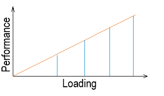
This step confirms that the systems not only work but also work reliably, efficiently, and safely under their intended operational loads.
5. Final Documentation:
The Operational Blueprint: Comprehensive documentation is the bedrock for future operation, maintenance, and potential troubleshooting.
- Detailed Test Results: All test data, observations, and readings from the commissioning process are meticulously recorded and compiled. This information establishes a crucial benchmark for evaluating future performance trends.
- Operation & Maintenance (O&M) Manuals: Comprehensive manuals are prepared, detailing operational procedures, maintenance schedules, troubleshooting guides, and safety precautions specific to the installed equipment and systems.
- Formal Stakeholder Sign-Off: The commissioning process concludes with formal sign-off from all relevant stakeholders, including the client, contractors, and regulatory bodies, indicating acceptance of the system’s performance and readiness for service.
Decommissioning: Powering Down Safely With Responsibility
Decommissioning serves as the essential counterpoint to commissioning, holding equivalent importance. Whether you are upgrading, relocating, retiring a system, or simply removing obsolete equipment, a structured decommissioning process ensures the equipment is safely isolated, removed, and disposed of in an environmentally responsible manner, minimising risks to personnel and the environment.

Key Stages of a Safe Electrical Decommissioning Process:
1. Planning and Assessment:
The Strategic Blueprint: Thorough planning is the cornerstone of a safe and efficient decommissioning.
- Site and System Review: A detailed review of the entire electrical installation, including its history, any modifications, and its interconnections with other systems.
- Risk Identification: Identifying all potential hazards, including electrical risks (stored energy, live conductors), mechanical risks (heavy equipment, moving parts), environmental risks (hazardous materials like old oils, PCBs, batteries), and any specific site-related dangers.
- Comprehensive Decommissioning Plan: Development of a detailed plan outlining every step, responsibilities, required permits, safety procedures, and a timeline for the entire process. This plan should include contingency measures for unexpected issues.
2. Isolation and Lockout/Tagout (LOTO):
The Safety Imperative: This is perhaps the most critical step in preventing accidental energisation and ensuring the safety of personnel.
- De-energisation of All Sources: Systematically disconnecting and de-energising all primary and secondary power sources, including utility feeds, generators, and Uninterruptible Power Supplies (UPS).
- Lockout/Tagout Procedures: Implementing strict Lockout/Tagout (LOTO) procedures. This involves physically locking circuit breakers or disconnects in the “off” position and placing tags to indicate that the equipment is undergoing maintenance and must not be re-energised
- Verification of Absence of Voltage: After LOTO, always verify the absence of voltage using a qualified voltage detector on all conductors before any work begins. This is a non-negotiable safety step.
3. Safe Disconnection:
Methodical and Mindful Removal: With the system safely isolated, the physical disconnection can begin.
- Methodical Wiring Disconnection: Systematically disconnecting wiring, labelling each wire or cable as it’s removed, if there’s any possibility of re-use, or to aid in understanding past installations. This prevents errors and streamlines the process.
- Handling Hazardous Components: Exercising extreme care when handling components that may contain hazardous materials, such as capacitors (which can store significant electrical charge even when de-energised), batteries (containing corrosive acids or heavy metals), or older transformers that might contain Polychlorinated Biphenyls (PCBs). Proper personal protective equipment (PPE) and specialised handling procedures are essential.
4. Disposal or Storage
Environmental Responsibility and Resource Management: This phase addresses the fate of the decommissioned equipment.
- Environmentally Compliant Disposal/Recycling: Equipment that is no longer usable must be recycled or disposed of in strict accordance with all local, national, and international environmental regulations. This often involves specialised recycling facilities for electrical waste (e-waste).
- Safe Storage of Reusable Parts: Components or equipment that are still functional and can be reused are carefully labelled, documented, and stored securely and appropriately to prevent damage or degradation.
5. Final Records
Completing the Lifecycle Documentation: The decommissioning process concludes with thorough documentation.
- Update Electrical Drawings and Logs: All electrical drawings, schematics, and equipment logs are updated to reflect the removal of the decommissioned equipment. This ensures that facility records are accurate and up-to-date.
- Comprehensive Documentation: A detailed record of the entire decommissioning process is created, documenting the date, scope of work, methods used, personnel involved, and any challenges encountered. This record is invaluable for auditing, compliance, and future planning.
Conclusion
Both commissioning and decommissioning are integral, non-negotiable phases in the lifecycle management of electrical equipment and installations. They are not merely regulatory hurdles but critical processes that ensure safety, optimise performance, extend asset life, and promote environmental responsibility. By adhering to these systematic methods, organisations can safeguard their investments, protect their personnel, and maintain the integrity of their electrical infrastructure from the moment of installation to the point of retirement. Investing in these processes is an investment in long-term operational excellence and safety.
Last reviewed date: 11/07/2025

Electrical Risk Management: Identifying Hazards, Assessing Risks and Applying Control Measures
Electrical Risk Management: Identifying Hazards, Assessing Risks and Applying Control Measures An el…

How to Become an Electrician in Australia (2026 Complete Guide)
How to Become an Electrician in Australia (2026 Complete Guide) An electrician installs, tests, main…

What Is UEE40420? A Complete 2026 Guide to the Certificate IV in Electrical Instrumentation
What Is UEE40420? A Complete 2026 Guide to the Certificate IV in Electrical Instrumentation UEE40420…
Leave a Reply